Projects/Led Board: Difference between revisions
< Projects
Jump to navigation
Jump to search
No edit summary |
No edit summary |
||
| (17 intermediate revisions by 3 users not shown) | |||
| Line 1: | Line 1: | ||
{{Project | {{Project | ||
|name=Led Board | |name=Led Board aka BitPanel | ||
|start=2012/10/03 | |start=2012/10/03 | ||
|contact= | |contact=Bobo1on1, Eightdot, Zarya | ||
|info=A matrix led board we got from someone | |info=A matrix led board we got from someone | ||
|status= | |status=Production | ||
|Picture=Ledbord1.jpg | |||
}} | }} | ||
== TODO == | |||
More info needed about the protocol!!! | |||
=== | == Hardware information == | ||
[[Projects/Led_Board/Hardware info]] | |||
[[File:bitpanel-schema.png|400px]] | |||
==== | == Movies == | ||
* http://youtu.be/uRoLeDcK8kE | |||
* Bitpanel playing gangnam style https://www.youtube.com/watch?v=i5fbJgMQjg8 | |||
* Bitpanel playing scene from resident evil https://www.youtube.com/watch?v=84-6v3la7Ro | |||
* Bitpanel playing the ridle https://www.youtube.com/watch?v=IwgmokQ91Yw | |||
== pics == | == pics == | ||
<gallery> | <gallery> | ||
| Line 130: | Line 33: | ||
</gallery> | </gallery> | ||
== | == New Hardware == | ||
<gallery> | |||
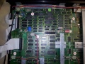
File:Zarya 21010.jpg|The 2 green boards at the bottom right are the old control boards the small pcb in the top right is the new hardware. | |||
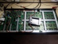
File:Zarya 21011.jpg| | |||
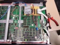
File:Zarya 21013.jpg|The new hardware contains a Raspberry PI, ATMega 644p and 3 74HC595 shift registers | |||
File:Zarya 21012.jpg| | |||
</gallery> | |||
Latest revision as of 23:26, 18 January 2014
 | |
|---|---|
| Project Led Board aka BitPanel | |
| Name | Led Board aka BitPanel |
| Start | 2012/10/03 |
| End | |
| Contact | Bobo1on1, Eightdot, Zarya |
| Website | |
| Information | A matrix led board we got from someone |
| Status | Production |
TODO
More info needed about the protocol!!!
Hardware information
Projects/Led_Board/Hardware info

Movies
- http://youtu.be/uRoLeDcK8kE
- Bitpanel playing gangnam style https://www.youtube.com/watch?v=i5fbJgMQjg8
- Bitpanel playing scene from resident evil https://www.youtube.com/watch?v=84-6v3la7Ro
- Bitpanel playing the ridle https://www.youtube.com/watch?v=IwgmokQ91Yw
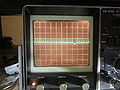
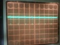
pics
sign displaying green
sign displaying red


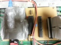
New Hardware
The 2 green boards at the bottom right are the old control boards the small pcb in the top right is the new hardware.
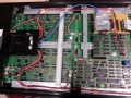
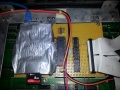
The new hardware contains a Raspberry PI, ATMega 644p and 3 74HC595 shift registers